



Liquid cooling solves the heat problems an air fan cannot reach inside a 3D printer, and the pump decides whether that loop stays quiet and reliable. The SC2201RPW gear pump circulates coolant at 20-50 mL/min below 60 dB for a single low-power loop, while the 24 V peristaltic SC2301CPW delivers 100 mL/min and above when the heat load is larger. Size the flow from the heat, then choose the coolant and the tubing.
Why a 3D printer needs a water cooling system
A 3D printing water cooling system earns its place when the heat source is enclosed, concentrated or continuous, because air can only carry heat into the air around it, while liquid carries that heat to a radiator you can place anywhere on the machine.
Heat creep is the clearest case. Inside a sealed chamber at 45-55 C the cold-end fan on a hotend recirculates warm air instead of cool air, the filament softens above the melt zone, and the nozzle clogs mid-print.
Chamber heat is the second case, and it is not only a print-quality issue. Published guidance for filament printers describes chambers held at around 60-70 C and states that a printer placed in a chamber should have electronics with active cooling to reduce the risk of fire.
Concentrated sources are the third. A diode laser module converts only part of its input power into optical output, so the remainder leaves as heat that has to be conducted away from a small package, and stepper motors with their drivers add a few watts each into the frame and the chamber air.
The manufacturer's field reports put the change in printer terms: moving a hotend to liquid cooling stabilised its temperature from swings of about 5 C to about 1 C or less and lifted print success rates from roughly 70 percent to more than 90 percent.
Why air cooling runs out of headroom
Water carries about four times the specific heat of air per unit mass - about 4.2 J/(g.K) against roughly 1.0 J/(g.K) - so the same heat load needs a far smaller mass flow of liquid than of air. That ratio, not the fan, is what makes a liquid loop attractive once the heat is trapped inside an enclosure.
The second advantage is routing. A fan can only reject heat into the air it sits in, which is the same air the part is printing in. A loop with an external radiator can reject that heat outside the chamber, so cooling and chamber temperature stop fighting each other.
Which heat sources liquid cooling actually suits
|
Heat source |
Where the heat goes |
Does liquid cooling help? |
|
Hotend heat break |
Continuous conduction up the filament path into the cold end |
Yes: a cold block on the heat break plus a radiator outside the chamber |
|
Stepper motors and drivers |
Into the frame, then into the chamber air |
Sometimes: heatsinks and airflow first, liquid only in a sealed chamber |
|
Enclosure electronics |
Into 60-70 C chamber air |
Yes, but the fix is active air cooling in an IP-rated enclosure, not coolant |
|
Diode laser or UV module |
Most of the input power leaves as heat |
Yes: a liquid cold plate is the standard solution as optical power rises |
|
Resin vat and wash station |
No heat, only fluid handling |
Not cooling, but the same pump family handles the fluid |
Table 1. Heat sources in a 3D printer, where each one goes, and whether a coolant loop is the right answer.
Sources: manufacturer fluid-system guidance (45-55 C chamber, hotend cooling field data) and the cited filament-fabrication reference (60-70 C chambers, actively cooled electronics); the laser, motor and electronics rows are engineering practice for this machine class.
Read next: How to choose a fluid system for 3D printers.
How much coolant flow does the loop need?
Flow follows the heat load, not the pump catalogue: required flow equals heat load divided by density, specific heat and the temperature rise you are willing to accept. At a 5 K rise, 50 mL/min of water carries about 17 W; at a 10 K rise the same flow carries about 35 W.
The flow equation in printer units
For water near room temperature the equation collapses into one constant: required flow in mL/min is about 14.4 times the heat load in watts divided by the allowed rise in kelvin. The constant is the reciprocal of density times specific heat, so it belongs to the coolant rather than to the pump.
Glycol changes that constant. A 1:1 mix by mass of glycol and water has a specific heat of about 3140 J/(kg.K), roughly three-quarters of water's, so it needs about 25 percent more flow for the same temperature rise. That is the price of freeze protection, and it is worth paying only when the machine has to survive below freezing.
|
Loop heat load |
Flow for a 2 K rise |
Flow for a 5 K rise |
Flow for a 10 K rise |
|
10 W |
72 mL/min |
29 mL/min |
14 mL/min |
|
20 W |
144 mL/min |
58 mL/min |
29 mL/min |
|
50 W |
360 mL/min |
144 mL/min |
72 mL/min |
|
100 W |
720 mL/min |
288 mL/min |
144 mL/min |
|
200 W |
1,440 mL/min |
576 mL/min |
288 mL/min |
Table 2. Coolant flow required to carry a given heat load at three temperature rises, for water at 25 C.
Source: author's calculation from Q = P / (rho x c x dT) with rho = 997 kg/m3 and c = 4180 J/(kg.K), giving Q in mL/min = 14.4 x P / dT. Use 17.9 x P / dT for a 1:1 water-glycol mix. Values are rounded.
Why more flow is not automatically better cooling
At 50 mL/min through a 2.5 mm bore the coolant travels at about 0.17 m/s, and the Reynolds number is roughly 420 at 20 C and 650 at 40 C - well inside the laminar band, which ends near 2,300. In that regime the film coefficient at the cold plate is set by the channel geometry and the fluid's conductivity rather than by how hard the pump pushes, so doubling the flow buys a smaller temperature rise in the fluid but does not halve the block's thermal resistance.
Pressure drop behaves the same way. In the Hagen-Poiseuille relation for a circular tube, flow resistance is inversely proportional to the fourth power of the radius, so bore matters far more than length. A 2.5 mm bore running 600 mm at 50 mL/min costs only about 0.3 kPa of straight-pipe friction; halving the bore multiplies that by sixteen.
In a real loop the fittings dominate anyway. Cold-plate micro-channels, quick-disconnects, elbows and filters account for far more resistance than the tube wall does, which is why the published 40-150 kPa of the SC2301CPW matters once a loop carries several fittings and a fine-pitch cold plate, while the SC2201RPW's rating of more than 30 kPa is comfortable for a short, simple circuit.
The reservoir is thermal mass, not the heat path
A reservoir absorbs transients rather than steady-state load. One litre of water takes in about 4.2 kJ for every kelvin it warms, so a 100 W pulse lasting a minute - 6 kJ - raises a one-litre reservoir by about 1.4 K, while a 100 mL reservoir would rise by about 14 K. Size the reservoir as a buffer, and use radiator area and flow for the duty that never stops.
Read next: The technical trade-off behind flow rate, pressure, and noise.
SC2201RPW: a quiet 3D printer water cooling pump
The SC2201RPW is a DC gear pump rated at 20-50 mL/min, more than 30 kPa and below 60 dB at 30 cm on 3, 6 or 12 V, which makes it a quiet water pump for a single low-power coolant loop rather than a high-flow radiator circuit.
What the published specification says
|
Parameter |
SC2201RPW specification |
What it means in a printer loop |
|
Pump type |
Gear, positive displacement |
Flow is proportional to motor speed, so PWM meters it predictably; there is no tube to replace |
|
Rated voltage |
DC 3 / 6 / 12 V |
Runs from a controller, a battery pack or a 12 V rail without a converter |
|
Flow rate |
20-50 mL/min |
Carries about 7-17 W at a 5 K rise, or about 14-35 W at 10 K (Table 2) |
|
Pressure |
More than 30 kPa |
Sufficient for a short loop with one cold block, an inlet filter and a few fittings |
|
Noise |
Below 60 dB at 30 cm |
About the level of normal conversation; suited to a bedroom or shared office |
|
Cycle life |
480,000 cycles tested at 5 s on, 3 s off |
A test description: in continuous circulation, plan tube and pump life in hours, not cycles |
|
Fluid contact |
Gear and housing |
Confirm coolant chemistry and keep a coarse inlet filter upstream of the pump |
|
Priming |
Not self-priming |
Keep the reservoir at or above the pump inlet so the inlet stays flooded |
Table 3. SC2201RPW parameters and what each one changes in a 3D printer coolant loop.
Source: manufacturer specification page for the SC2201RPW; the heat-carried column is the author's calculation from Table 2.
Why 20-50 mL/min is the right size for one loop
A single hotend cold-end loop is a low-power load. At 50 mL/min and a 10 K rise the SC2201RPW is already moving about 35 W of heat, which is more than a single heat break rejects in normal duty - an engineering estimate for this machine class rather than a published figure - and a short loop with the manufacturer's reference bore needs well under 30 kPa to run.
Low flow is a feature here, not a compromise. Running this quiet water pump at 20-50 mL/min keeps noise, motor heat and every wear surface low, because they all rise with speed, while the heat a single low-power loop has to move does not. A slower loop is the correct engineering trade for this duty, and it is why a sub-60 dB rating and a 20-50 mL/min flow range belong to the same pump.
Control is straightforward because flow tracks motor speed. A spare PWM output gives repeatable flow, and the published guidance is to move the switching band to 20-25 kHz and keep the minimum command above the dead zone, where the pump would otherwise hum and warm its winding without moving fluid.
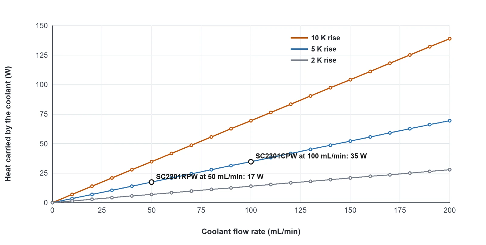
Figure 1. Heat carried by a water loop at three temperature rises, with the two pumps' published flow ranges marked.
Source: author's calculation from Q = P / (rho x c x dT) for water at 25 C, plotted against the manufacturer's published flow ranges for the SC2201RPW (20-50 mL/min) and the SC2301CPW (100 mL/min and above). A calculation, not a measurement.
Read next: SC2201RPW micro gear pump for resin refill.
Peristaltic pump cooling: fluid isolation and high flow
The SC2301CPW is a 24 V peristaltic pump rated at 100 mL/min and above, 40-150 kPa, 60 dB or less at 50 cm and 200 mA or less. It is the pump to specify when the loop must carry more heat, tolerate air bubbles, or keep the electronics completely out of the fluid path.
What the published specification says
|
Parameter |
SC2301CPW specification |
What it means in a printer loop |
|
Pump type |
Peristaltic, positive displacement |
Liquid touches the tube only; there is no shaft seal to leak or to contaminate the coolant |
|
Rated voltage |
DC 24 V |
Matches common printer supplies and can run from the mainboard |
|
Flow rate |
100 mL/min and above |
Carries about 35 W at a 5 K rise, or about 70 W at 10 K (Table 2) |
|
Working pressure |
40-150 kPa |
Covers cold-plate micro-channels, quick-disconnects, elbows and filters |
|
Noise |
60 dB or less at 50 cm |
About the level of normal conversation, and often quieter than the printer's own stepper motors |
|
Current draw |
200 mA or less (under 5 W at 24 V) |
Runs from a fan-style output once the MOSFET rating is confirmed |
|
Priming |
Self-priming; tolerates small bubbles and particles |
Simplifies filling, bleeding and restarting a loop after service |
|
Consumable |
The tube, replaced in about two minutes |
Budget a tube swap on hours of running, not on a cycle headline |
Table 4. SC2301CPW parameters and what each one changes in a 3D printer coolant loop.
Source: manufacturer specification summary for the SC2301CPW; the heat-carried column is the author's calculation from Table 2.
One caution on the noise figures. The two pumps are not published at the same distance: below 60 dB at 30 cm for the SC2201RPW, against 60 dB or less at 50 cm for the SC2301CPW. Sound pressure falls by about 6 dB each time the distance doubles, so 60 dB at 50 cm is roughly 64 dB at 30 cm in free field. On a like-for-like basis the two figures are close, so the quieter-looking number is a measurement distance rather than a design difference.
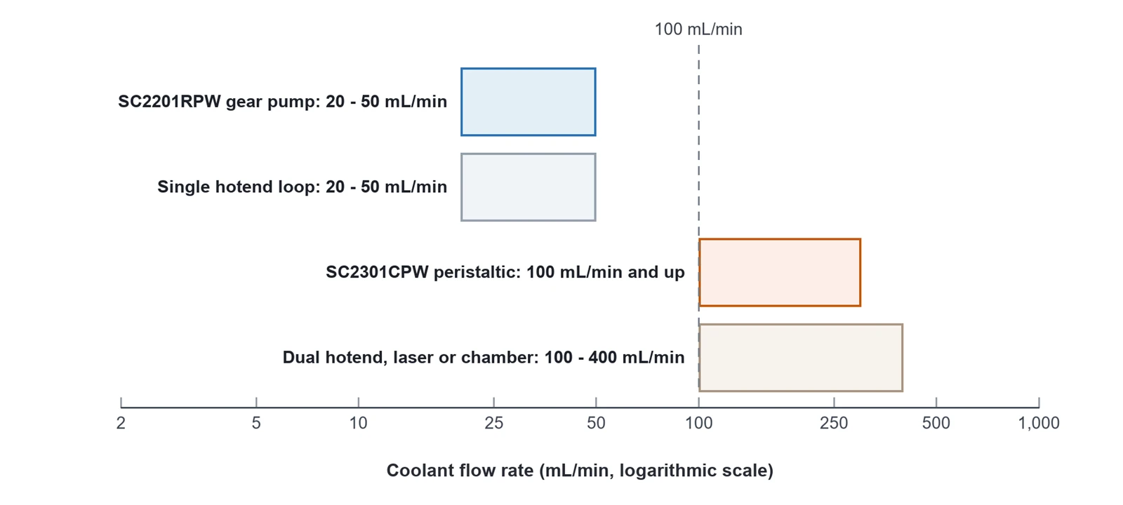
Figure 2. Coolant flow ranges for the two pumps against the flow that common printer loops need.
Sources: manufacturer published flow ranges for the SC2201RPW (20-50 mL/min) and the SC2301CPW (100 mL/min and above); the loop bands are derived from Table 2 at a 10 K temperature rise. A calculation, not a measurement.
SC2201RPW or SC2301CPW: which pump for which loop
|
SC2201RPW |
SC2301CPW |
|
|
Pump type |
Gear, positive displacement |
Peristaltic, positive displacement |
|
Voltage |
DC 3 / 6 / 12 V |
DC 24 V |
|
Flow rate |
20-50 mL/min |
100 mL/min and above |
|
Pressure |
More than 30 kPa |
40-150 kPa |
|
Noise |
Below 60 dB at 30 cm |
60 dB or less at 50 cm |
|
Heat carried at a 10 K rise |
About 14-35 W |
About 70 W and above |
|
Fluid contact |
Gear and housing |
Tube only |
|
Self-priming |
No |
Yes |
|
Consumable |
None; keep an inlet filter |
The tube |
|
Best for |
Quiet, compact, low-power circulation and dosing |
Higher heat loads, fluid isolation and bubble tolerance |
Table 5. SC2201RPW and SC2301CPW side by side, with the heat each can carry in a water loop.
Sources: manufacturer specification pages for both models; the heat-carried row is the author's calculation from Q = 14.4 x P / dT.
"Gear pump high-flow cooling": what the search term really means
Buyers who search for gear pump high-flow cooling are usually describing the job rather than the hardware. In this family the gear pump is the metering device: the SC2201RPW moves 20-50 mL/min, which is a low-flow pump by any cooling standard. High-flow cooling duty is served by the peristaltic SC2301CPW at 100 mL/min and above, or by a centrifugal pump when a loop needs litres per minute at low pressure.
The distinction matters because flow and pressure trade against each other rather than adding. Both pumps are positive displacement, so they hold flow as system resistance rises, but their absolute flow is set by displacement and speed, not by how hard the motor is driven. If a loop has to move more than about 70 W at a 10 K rise, the 100 mL/min peristaltic pump is the starting point; below about 35 W, the quiet gear pump covers the duty.
|
Free loop sizing review. Send the heat load in watts, the allowed temperature rise, the loop length and the coolant you intend to use. We will return the flow and pressure your loop needs, a pump recommendation from the two models above, the bore and tube material to specify, and sample terms for a bench test. |
Read next: Peristaltic pump vs gear pump for 3D printers.
Coolant selection for a 3D printer water cooling system
Distilled water with a corrosion inhibitor and a biocide is the default coolant for a printer loop. Glycol is added only when the machine has to survive below freezing, because it gives up roughly a quarter of the loop's heat capacity and buys nothing at room temperature.
Water, glycol, or a pre-mixed coolant
|
Coolant |
Specific heat |
Freeze protection |
Use it when |
Watch out |
|
Distilled water plus inhibitor and biocide |
About 4.2 J/(g.K) |
None |
The machine stays above 0 C |
Needs both additives: biocide against algae, inhibitor against mixed-metal corrosion. Never use tap water long term |
|
Water and glycol, 1:1 by mass |
About 3.1 J/(g.K) |
About -37 C at 50 percent by volume |
The loop is stored, shipped or operated below freezing |
About 25 percent more flow for the same rise; higher viscosity; keep it inhibited |
|
Pre-mixed printer or PC coolant |
Formulation dependent |
Formulation dependent |
You want inhibitor and biocide in one bottle |
Check compatibility with the tube, the block and any acrylic in the loop |
Table 6. Coolant options for a printer loop, with the property that changes the flow calculation.
Sources: specific heat and thermal conductivity of water from the cited water reference; 1:1 by mass glycol at about 3140 J/(kg.K), and pure glycol at about half the specific heat of water, from the cited glycol reference; the -37 C figure for a 50 percent by volume propylene glycol mix with a pressurised system from the cited antifreeze reference.
Mixed metals: the corrosion trap in every printer loop
A printer loop usually mixes metals without anyone deciding to: an aluminium cold block, a copper or brass radiator, brass fittings and a stainless clamp. Where two dissimilar metals share a conductive fluid, the pair forms a galvanic cell and the less noble metal corrodes. This is the same problem that makes automotive coolant carry corrosion inhibitors, because a vehicle cooling system contains aluminium, cast iron, copper, brass and solder at the same time.
Two rules follow. Keep the loop to one metal family where you can, and always run an inhibited coolant rather than bare water. Inhibitors used in water systems include sodium nitrite and sodium molybdate. Add a biocide as well: light and warmth grow algae in an untreated loop, and the biofilm then blocks the cold plate and feeds particles into the pump.
Condensation: the cold-plate trap in a heated chamber
The colder the coolant, the more heat it can absorb, so chilling the reservoir is tempting. In a heated chamber it is a mistake. Chamber air in this printer class sits near 60-70 C, and against a cold plate held well below the chamber's dew point, water condenses out of the air directly onto the block, the fittings and anything below them.
Keep the coolant above the chamber dew point, insulate the cold block and its lines, or split the loop into a sealed primary circuit and a secondary chiller circuit. Never route the loop above the power supply or the controller.
Read next: Solving clogs, bubbles and leaks from micro pump parameters.
Cooling pipe selection: tubing, bore and fittings
Choose tubing in this order: a material that survives the pump mechanism, a chemistry that survives the coolant, then the bore and the length that your flow calculation asked for. Everything else is detail.
Material: what the rollers and the coolant will tolerate
|
Material |
Hardness / form |
Temperature |
Over rollers |
With water and glycol |
Watch out |
|
Silicone |
25-90 Shore A; 45 Shore A in the reference test loop |
About -101 to 299 C |
Yes: the standard choice, best flex life |
Good |
High gas permeability, so air migrates in and forms bubbles; swells in some solvents |
|
EPDM |
30-90 Shore A |
-50 to 150 C |
Fair |
Good, and strong against heat, ozone and weather |
Degrades in contact with bituminous material; check resin and cleaner compatibility |
|
PTFE |
Rigid; coefficient of friction 0.05 to 0.10 |
Stable to about 260 C |
No: low flex life, it cracks over rollers |
Excellent, almost chemically inert |
Use it for the static run and the cold-plate tail only |
|
PVC |
Rigid or flexible, usually clear |
Low |
No |
Fair |
Plasticiser can leach into the coolant; poor heat resistance |
Table 7. Tube materials for a printer coolant loop, judged on the criteria that actually decide the choice.
Sources: silicone hardness range and its low tensile strength and poor wear resistance from the cited silicone reference; EPDM hardness, service range and bitumen warning from the cited EPDM reference; PTFE friction coefficient and thermal stability from the cited PTFE reference; the 45 Shore A and 2.5 mm bore test conditions from the manufacturer specification summary. Rows without a cited figure are engineering practice for this machine class.
Bore, length and bend radius
The bore comes from your flow calculation, not from the barb you happen to own. The manufacturer tests this pump family with a 2.5 mm bore, which is a sensible reference point: it keeps the loop in the laminar band at 20-50 mL/min and keeps pressure drop low enough for a pump rated at more than 30 kPa.
Keep the suction run short, straight and as wide as the pump inlet allows, because friction and trapped air hurt most before the pump. Keep the total loop volume small, since it sets how long bleeding takes and how much coolant a service costs. And respect the bend radius: a kinked tube is a closed valve with no warning, so route with generous curves and support long runs so the tube cannot collapse under suction.
Fittings, clamps and quick-disconnects
Every fitting adds pressure drop and a leak path, so count them before choosing the pump. Barbed fittings with a clamp suit soft silicone tubing; push-to-connect fittings suit rigid tube and are faster to service, at the cost of a seal that eventually needs replacing.
Fit a coarse inlet filter upstream of the pump. The gear pump is the reason: particles wear the gear mesh, and a worn mesh opens the clearances that set the pump's flow. On a peristaltic pump the filter protects the tube from abrasion instead.
Read next: 3D printer peristaltic pump: quiet micro liquid supply guide.
Installation and commissioning
Install the pump below the reservoir, keep the suction run short, put the reservoir at the highest point with a bleed at the cold block, and keep every electrical part above the fluid. Those four rules prevent most of the faults in section 8.
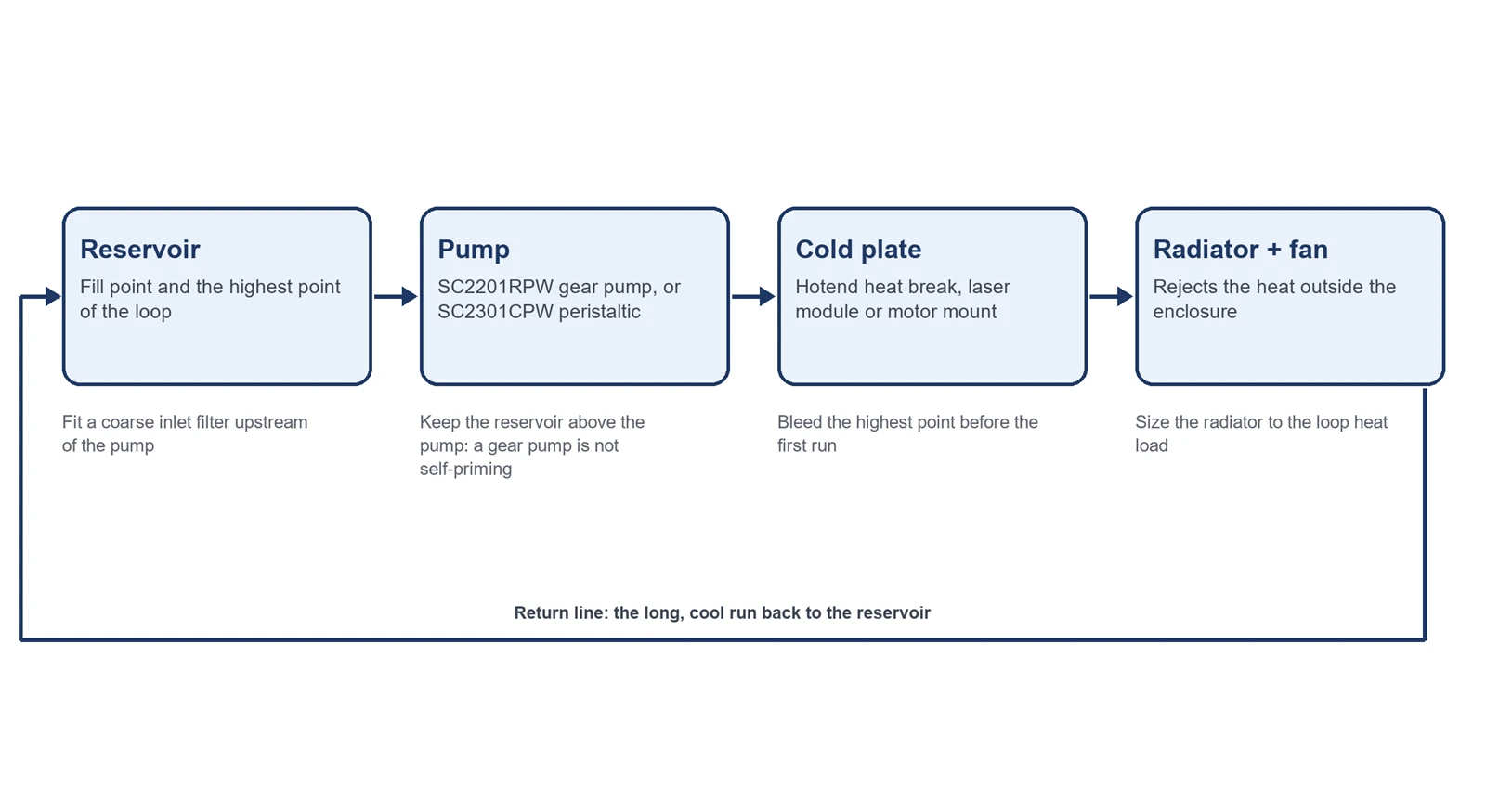
Figure 3. A printer coolant loop in the order the fluid travels, with the four installation rules that matter most.
Source: author's diagram. Component order follows standard closed-loop liquid-cooling practice; the priming rule reflects the published note that the SC2201RPW is not self-priming.
Baseline. Record the ambient temperature, the coolant temperature in the reservoir, the cold-plate temperature at steady state, the flow rate from a timed dose into a measuring cylinder, and the pump current.
Mount and flood. Put the reservoir at or above the pump inlet so a gear pump primes by gravity, isolate the pump from the frame, and fit the inlet filter. A peristaltic pump self-primes, but keep its inlet flooded anyway for stable flow.
Route and bleed. Fill the loop, then run the pump at low duty with the highest fitting cracked open until the returning stream is bubble-free. Tilt the machine to move trapped air toward the bleed point.
Protect the electrics. Enclose the driver to an IP rating that suits the location, using the IEC 60529 enclosure classification, keep cable entries below the loop, and set a drip tray under the joints. Never route tubing above the power supply.
Set the drive. Move the PWM band to 20-25 kHz, set the minimum command above the dead zone, and confirm the MOSFET rating, branch fuse and flyback diode if the pump shares a fan port.
Verify and log. Repeat the baseline after 24 hours of printing, then on the maintenance interval. A change that does not survive a day of heat is not a settled configuration.
|
What to record |
How to measure it |
Acceptance |
Recheck |
|
Ambient temperature |
Room or chamber thermometer beside the machine |
Inside the pump's published ambient range |
Weekly |
|
Coolant temperature |
Probe in the reservoir |
Stable at the set point |
Weekly |
|
Cold-plate temperature |
Thermocouple on the block, at steady state |
Within the target band for the hotend or module |
Weekly |
|
Flow rate |
Timed dose into a graduated cylinder at fixed duty |
Within 5 percent of the commissioned volume |
Every 40 hours |
|
Pump current |
Clamp meter on the pump supply |
Within 20 percent of commission |
Every 40 hours |
|
Tube condition |
Inspect at the roller track |
No flat spots, swelling or damp rings |
Weekly |
Table 8. A commissioning and maintenance record for a printer coolant loop.
Sources: the 40-hour dose and current checks with their 5 percent and 20 percent criteria, and the weekly tube inspection items, follow the published fluid-system maintenance guidance; the cold-plate row is engineering practice for this machine class.
Read next: 3.0 V or 24 V? Can your 3D printer mainboard actually drive this pump?.
Troubleshooting a coolant loop
Most coolant-loop faults appear as a temperature that will not settle, and the cause is usually flow, air or chemistry rather than the pump itself. Compare against the commissioning record before changing any hardware.
|
Symptom |
Likely cause |
What to check |
Corrective action |
|
Block temperature climbs slowly over hours |
Flow below the commissioned value, or a partly blocked cold plate |
Timed dose against baseline; inlet filter; block inlet and outlet temperature difference |
Clean the filter and the block; replace the tube on a peristaltic pump; re-check the flow calculation |
|
Temperature stable but too high |
Radiator or airflow undersized for the load |
Radiator air inlet and outlet temperatures; fan speed |
Add radiator area or airflow before adding flow |
|
Flow drops to zero under load |
Air locked in the loop, or a kinked suction line |
Bubbles at the return; the suction run for flattening |
Re-bleed the loop; re-route the suction line with a larger bend radius |
|
Pump current above baseline and rising |
Cold or viscous coolant, a restriction, or wear |
Coolant temperature and mix ratio; clamp-meter reading |
Restore the coolant mix; clear the restriction; service the pump |
|
Water on the frame or under the machine |
Fitting or tube failure, or condensation |
Trace the drip path, then inspect the cold block |
Reseat or replace the fitting; insulate the block; keep the coolant above the dew point |
|
Noise that follows the duty setting |
Drive and motor mismatch |
Change the PWM frequency at constant duty |
Move the band to 20-25 kHz and screen the wiring |
Table 9. Troubleshooting matrix for a printer coolant loop.
Sources: the dose and current criteria follow the published maintenance guidance; the air-lock, radiator and condensation rows are engineering practice for this machine class.