



3D printer pump noise reduction usually starts away from the pump: the mount, the tubing and the drive setting carry most of the sound. Fix the mounting path first, move the PWM band to 20-25 kHz second, and protect the wear part third. A published 60 dB figure is a test condition rather than a promise for your machine, so measure at 30 cm before and after every change.
Where 3D printer pump noise reduction starts
A pump makes noise in three separate places, and each takes a different fix: the fluid path, the motor and its drive, and the structure the pump is bolted to.
The manufacturer's fault list names five causes, and three are maintenance problems: idling, scale, and a blocked inlet that shivers under negative pressure. The other two are a drive mismatch that adds a faint high-frequency tone and rotor-and-shaft tolerance, named as the biggest source of all - a design variable no bracket can cure.
Brush motors add a second signature: carbon-brush wear produces sparks and noise, and fluid reaching the stator-rotor gap can damage the motor.
How to separate PWM whine from mechanical noise
Three tests separate the sources before you buy anything. Hold the duty constant and change only the PWM frequency: if the tone moves, the noise is electrical. Press on the bracket while the pump runs: if the loudness changes, the frame is radiating. Compare a cold start with a thirty-minute run: a rumble that grows over weeks points to scale, while noise that starts the moment the reservoir empties points to idling.
|
Noise source |
Published signature |
Confirmation test |
Corrective action |
|
Idling (no liquid) |
Noise rises sharply |
Run flooded, then briefly with air (inside the 20-second dry-run limit) |
Prime before starting; keep the inlet flooded |
|
Scale and deposits |
Progressive rumble over weeks |
Compare a fresh-fluid flush with the fluid in use |
Flush, filter and correct the fluid chemistry |
|
Mismatched electronics |
Faint high-frequency tone |
Change the PWM frequency at constant duty |
Move the band to 20-25 kHz; screen the wiring |
|
Rotor and shaft tolerance |
Loud at every speed, flooded or dry |
Run a second unit of the same model alongside |
Specify the tolerance; check it on the sample |
|
Structure-borne coupling |
Changes when the mounting or panel changes |
Press on the bracket while the pump runs |
Isolate the mount; remove rigid bridges (section 3) |
Table 1. Pump noise sources, the published signature of each, and the test that identifies it.
Sources: manufacturer noise troubleshooting note and specification summary; the structure-borne row is engineering practice, not a published measurement.
Read next: Micro DC water pump noise solutions.
Measure the noise before you modify the pump
A baseline taken the same way twice beats any advertised figure. Record the level at 30 cm and 1 m at the duty you run, with the machine assembled, and note the distance and mounting every time.
The two published figures are not comparable. The 3 V pump is below 60 dB at 30 cm, measured at 5 V DC on a 5 cm sponge; the 24 V pump is published at 60 dB at 50 cm with no mounting condition stated. Sound pressure falls about 6 dB each time the distance doubles, so 60 dB at 50 cm is roughly 64 dB at 30 cm in free field. On a like-for-like basis, both pumps are not under 60 dB.
Use one phone app for before-and-after comparison, but a meter to IEC 61672-1 when the number will be published, because a phone has no stated weighting. Judge the level at arm's length, where the listener sits.
Read next: Peristaltic vs gear pump for 3D printers.
Shock-absorbing installation for 3D printer pump noise reduction
An isolator is a spring and a damper together, and it behaves like a mechanical low-pass filter: above its natural frequency it reduces transmission, at resonance it amplifies it. That is why the same rubber pad can make one printer quieter and another one louder.
3D printer pump shock-absorbing installation
Load and geometry matter more than material. Keep the working compression inside the isolator's elastic range, because a squashed pad is a rigid link, and keep the isolator's natural frequency well below the frequency the pump excites.
|
Material |
Hardness (Shore A) |
Service temperature |
Where it fits |
Watch out |
|
EPDM |
30-90 |
-50 to 150 C |
Brackets, feet and pads exposed to heat, ozone and weather |
Degrades in contact with bituminous material |
|
Silicone rubber |
25-90 |
-101 to 299 C |
Grommets and washers near a heated enclosure |
Low tear resistance; avoid thin cut pads |
|
Foam sponge (as tested) |
Not stated |
Not stated |
The only mounting the manufacturer documents: a 5 cm sponge under the pump |
Material and density are not published |
Table 2. Elastomer properties for pump mounts, with the mounting used in the published noise test.
Sources: EPDM and silicone property tables from the cited polymer references; mounting row from the 3 V pump product page. 'Not stated' means the cited source does not publish the value.
The five ways a shock-absorbing retrofit fails
Bridging the isolator. A bolt through the pad, a cable tie or a rigid bracket creates a parallel path, and the elastomer then does nothing.
Rigid tubing. The documented test conditions use 45 Shore A silicone with a 2.5 mm bore and 350 mm inlet and 250 mm outlet runs. A short stiff tube transmits vibration: too hard may not seal at the barb, too soft can collapse under suction.
Mounting on the wrong frequency. A soft pad under a light bracket can put the mount's natural frequency inside the pump's excitation range, where it amplifies instead of isolating; more bracket mass or a damper flattens that peak.
Bypassing the isolator with wiring. Every cable or tube that crosses the gap is a vibration short-circuit; leave a service loop in each one.
Over-torquing the fasteners. Compression past the elastic range turns the isolator into a rigid spacer.
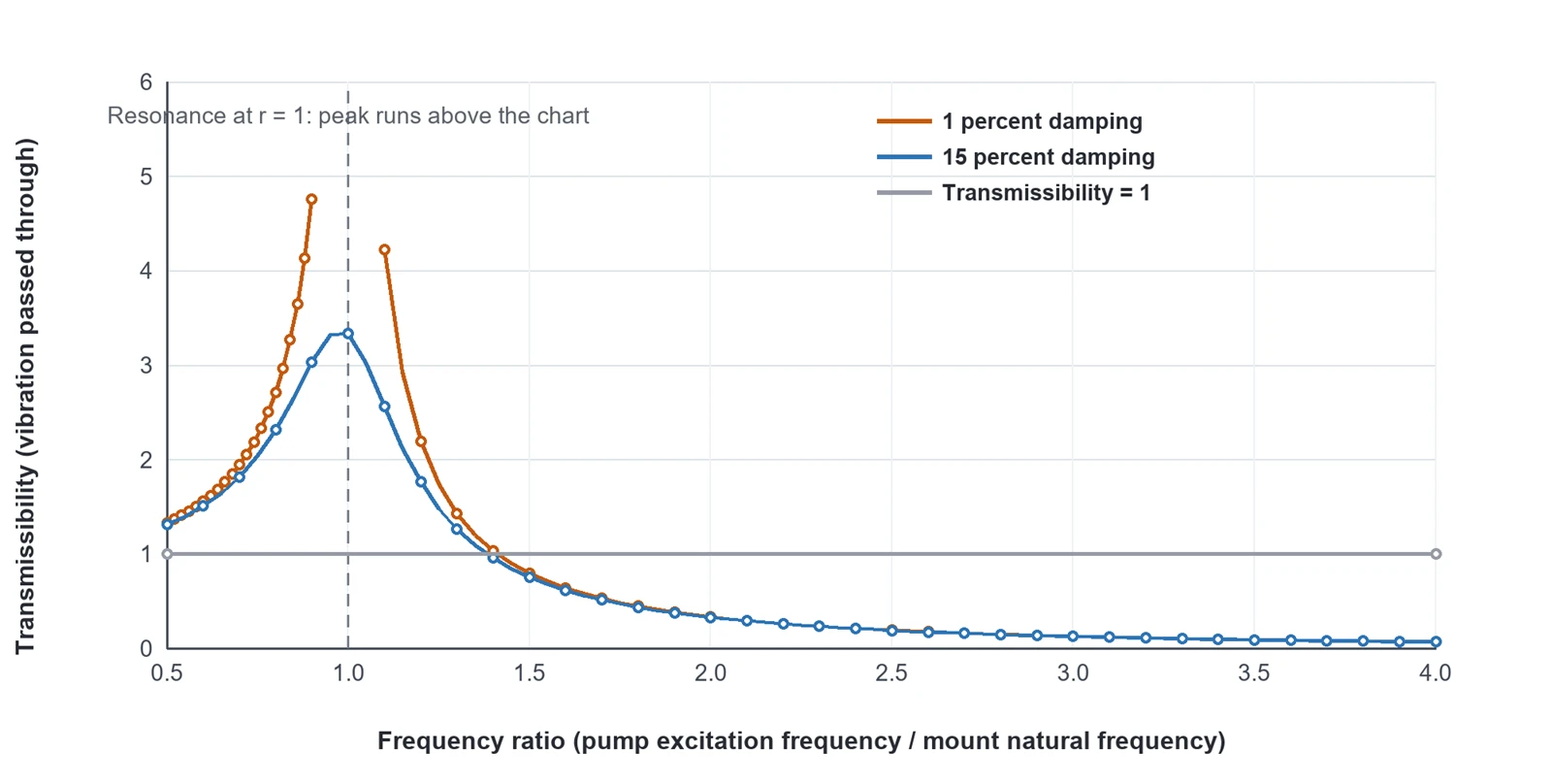
Figure 1. Modelled transmissibility of a pump mount: vibration is amplified at resonance and attenuated only above the crossing point, and more damping lowers the peak.
Source: author's model using the standard single-degree-of-freedom transmissibility relation T = 1 / sqrt((1 - r^2)^2 + (2 zeta r)^2) for r = f/fn, combined with the published finding that a passive isolator is a mechanical low-pass filter. A model, not a measurement.
Read next: SC2301CPW 24 V pump specification.
Quiet modification with peristaltic pump PWM speed control
PWM sets speed by duty and the sound by switching frequency. The published starting points are 20 kHz, a 20-25 kHz band for silent duty, and a warning that beyond roughly 30-40 kHz a small driver spends real power just switching.
At low duty the pump enters a dead zone where friction and load torque stop it starting: it hums, heats the winding and moves nothing. Set the minimum command above the reliable start point, and prefer a driver that already handles commutation, current limiting and soft-start.
Quiet modification: choosing the frequency band
Figure 2 places the recommendation against the audible band. Human hearing spans roughly 20 Hz to 20 kHz, so switching at 20-25 kHz removes the electrical whine, while above 30-40 kHz switching losses start to cost real power and heat.
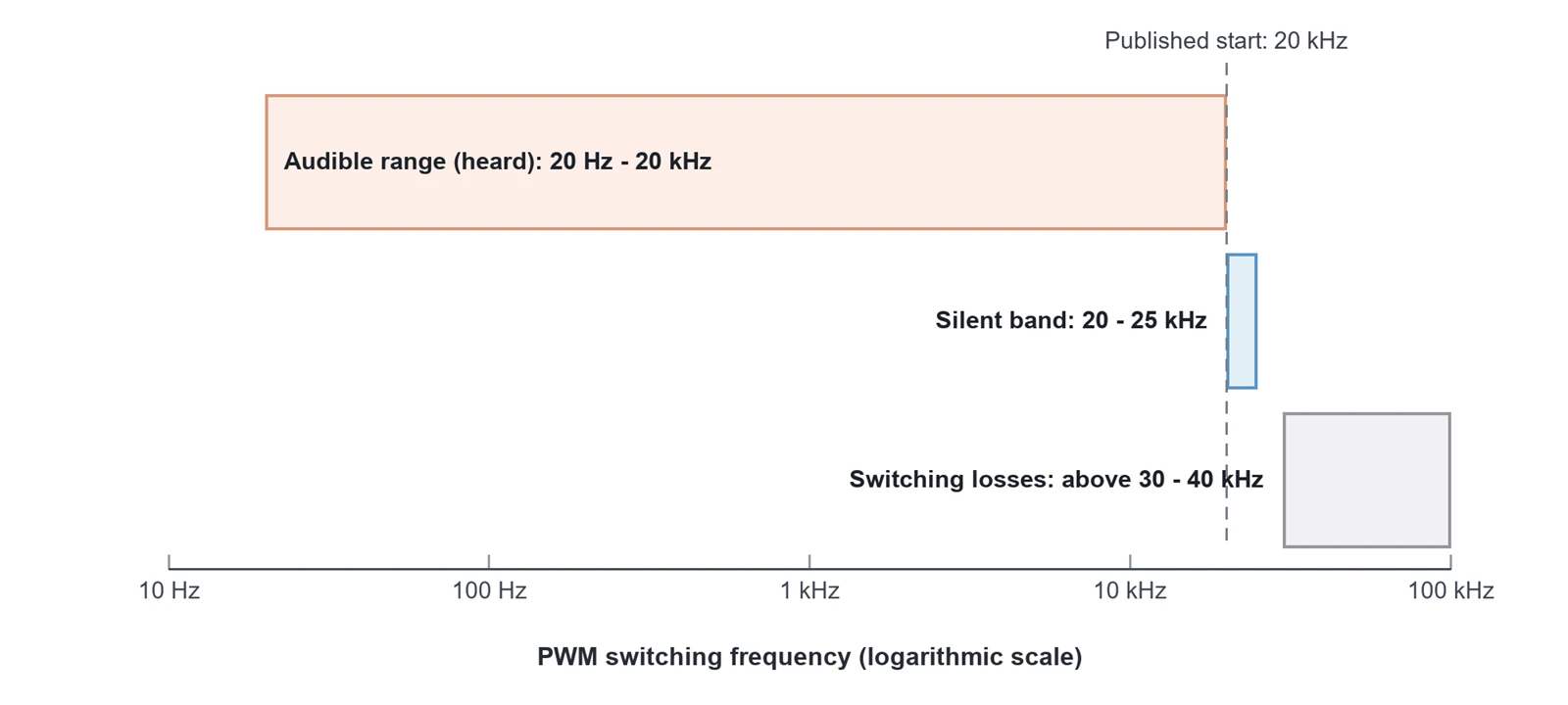
Figure 2. Published PWM switching bands against the audible range of human hearing.
Sources: manufacturer PWM application guide (20 kHz starting point, 20-25 kHz silent band, switching losses above roughly 30-40 kHz); hearing range of 20 Hz to 20 kHz from the cited acoustics reference.
Wiring: keep the electrical noise out of the printer
A brushed motor's commutation noise does not stay in the pump wiring: in a printer it can couple into thermistor signals or stepper-driver reference voltages and cause erratic readings. Keep pump wiring away from thermistor and endstop runs, keep the return path short, and screen long runs.
Printer MCUs supply roughly 25-40 mA per pin and 150-200 mA across their supply pins, while small pumps draw 100-500 mA, so a fan port needs its MOSFET, fuse and rail headroom confirmed first. Use a low-side logic-level MOSFET rated for stall current with a branch fuse and a flyback diode, and size the supply for inrush: a converter changes voltage but never creates current.
|
Free retrofit review. Send the pump model, a photo of the mounting and your current PWM settings. We will return the isolator and tubing recommendations, a safe starting drive band, and the baseline numbers worth logging weekly. |
Read next: How PWM affects micro pumps.
Lifespan extension modifications
Life is spent by heat, dry running and hours under load, so the modifications that extend it are thermal, hydraulic and operational rather than acoustic.
Peristaltic pump lifespan: protect the tube
The tube decides peristaltic pump lifespan, and published guidance for printer refill duty is several months to a year. Release the occlusion when the machine is idle, because a tube held compressed keeps taking a compression set - the mechanism covered by standard compression-set testing - and keep the documented geometry: 45 Shore A silicone, a 2.5 mm bore, and 350 mm inlet with 250 mm outlet runs.
Cycle ratings deserve the same scepticism as noise figures. The product page states more than 300,000 cycles at a 5-second-on, 3-second-off pattern, plus a separate test reaching 600,000 delivery cycles, while an application article quotes a tested 480,000-cycle life. Treat each as a test description and plan tube replacement on hours, not on a cycle headline.
Gear pump maintenance: clearances and priming
Gear pump maintenance starts with the fluid, which is both lubricant and bearing. The published specification prohibits dry running beyond 20 seconds, because the gears wear against the housing and open clearances permanently, and a blocked outlet does not stop the pump: it raises internal leakage, heat and wear. Filter the inlet, prime before every start, and hold the 5-45 C ambient range with airflow around the motor end cap.
|
Modification |
Mechanism |
Expected effect |
Evidence level |
|
Isolate the mount and remove rigid bridges |
Structure-borne vibration is filtered instead of amplified |
The frame stops acting as a loudspeaker; usually the largest change in perceived noise |
Engineering practice; the published noise test rested the pump on a 5 cm sponge |
|
Move the PWM band to 20-25 kHz |
Switching noise moves above the 20 kHz hearing limit |
Removes the electrical whine; no effect on fluid-path noise |
Manufacturer PWM guidance |
|
Set the minimum duty above the dead zone and enable soft-start |
Avoids stall hum and winding heat |
Quieter start-up; lower winding temperature |
Manufacturer PWM guidance |
|
Peristaltic pump lifespan: release the occlusion when idle |
Slows compression set in the tube |
Longer tube life at stable flow |
Manufacturer maintenance guidance; mechanism per ASTM D395 |
|
Prime and filter; never dry-run a gear pump past 20 seconds |
Removes dry wear on gears and brushes |
Longer gear and bearing life; stable pressure |
Manufacturer specification summary |
Table 3. Retrofit modifications, the mechanism behind each, and the strength of the evidence.
Sources: manufacturer PWM application guide, fluid-system maintenance guidance, the 24 V specification summary and the 3 V product page; compression-set mechanism per ASTM D395.
Read next: SC2201RPW pump for resin refill.
Gear pump troubleshooting and state-based maintenance
The fastest gear pump troubleshooting path is arithmetic rather than guesswork: compare today's flow, current and pressure with the numbers recorded at commissioning. Most fluid-system failures trace back to five variables - displacement per revolution, working pressure, viscosity, suction condition and duty cycle - so finding which one moved is most of the diagnosis.
The published gear pump maintenance plan supplies the criteria. Every 40 hours of pump time, run a timed dose check and a current reading: the dose within 5% of the commissioned volume, the current within 20%. Weekly, inspect the tube at the roller track for flat spots, swelling and damp rings, and clean the inlet strainer. Monthly, re-verify calibration after any fluid change. Quarterly, replace the strainer, verify the minimum start command, and check the flyback diode.
|
Symptom |
Likely cause |
What to check |
Corrective action |
|
Flow below the commissioned value |
Tube compression set, gear clearance wear, filter loading |
Timed dose test; the tube at the roller track; strainer pressure drop |
Replace the tube; clean or replace the strainer; re-baseline a gear pump |
|
Current 20% above baseline, or rising |
Blockage, cold or thick fluid, wear |
Fluid temperature and viscosity; inlet restriction; clamp-meter reading |
Warm or thin the fluid; clear the restriction; schedule service |
|
Shivering or pulsing under load |
Blocked or restricted inlet |
Strainer, inlet bore, kinked tubing |
Clear the inlet; widen or shorten the suction run |
|
High-frequency tone that follows the PWM setting |
Drive and motor mismatch |
Change the frequency at constant duty; check the driver |
Move the band to 20-25 kHz; screen and route the wiring |
|
Loud at every speed, flooded and dry |
Rotor and shaft tolerance |
Run a second unit of the same model for comparison |
A design-level noise source: specify the tolerance and inspect samples |
Table 4. Troubleshooting matrix for printer pumps, built from the published fault and maintenance lists.
Sources: manufacturer noise troubleshooting note; fluid-system maintenance guidance (40-hour interval, 5% dose and 20% current criteria).
Read next: Solving clogs, bubbles and leaks.
A retrofit sequence for one weekend
Do the cheap, reversible steps first, and measure after each one so you know which change actually worked.
Baseline. Record the level at 30 cm and 1 m at the working duty, plus a timed dose, motor current, delivery pressure and ambient temperature.
Mount. Fit elastomers loaded inside their elastic range, remove anything that bridges the pad, and leave a service loop in every tube and cable.
Fluid path and drive. Keep the documented tube hardness and bore, prime with the inlet flooded, set the PWM band to 20-25 kHz above the dead zone, and confirm the MOSFET, fuse and flyback diode if the pump is wired to a fan port.
Re-measure and log. Repeat the baseline exactly, then repeat it after 24 hours of printing: a change that does not survive a day of heat is not a fix.
Read next: Silent but powerful: 24 V printer pump.
What a retrofit cannot fix
The biggest published noise source in this family is rotor and shaft tolerance, decided at design and manufacturing. A pump that is loud at every speed, flooded or dry, will not become quiet because of a bracket or a PWM setting: specify the tolerance and check it on the sample.
Maintenance problems are not acoustic problems either. A blocked inlet, scale and a worn tube all raise noise and all consume life, so the cheapest noise reduction is often the service the machine is already owed.
Five published claims also conflict, and each should be settled in writing before this guidance reaches a specification. The same model numbers are described as gear pumps on some pages and peristaltic pumps on others. One duty pattern carries three cycle figures: more than 300,000, a tested 480,000, and up to 600,000. The voltage set is listed as 3/5/8 V and as 3/6/12 V. One page states there is no tubing consumable while the product page describes a silicone tube fluid path. The same pump is quoted at more than 30 kPa and at not less than 6 psi, about 41 kPa.
Read next: 3.0 V or 24 V? Mainboard matching.
Key takeaways
Separate the three noise paths before buying anything: the fluid path, the motor drive and the structure the pump is bolted to.
An isolator is a low-pass filter, not a sponge: it amplifies at resonance and attenuates above that point, so load, bracket mass and geometry matter more than material.
Never bridge the isolator: a bolt through the pad, a cable tie or a rigid tube run puts the vibration straight back into the frame.
20-25 kHz is the published quiet PWM band; below the reliable start duty the pump only hums and heats the winding.
MCU pins supply 25-40 mA while small pumps draw 100-500 mA: use a MOSFET rated for stall current with a fuse and a flyback diode, sized for inrush.
Lifespan follows the same fixes: release the tube occlusion when idle, replace the tube at 500 hours or two-thirds of life, and never dry-run a gear pump past 20 seconds.
Frequently asked questions
How much can 3D printer pump noise reduction achieve?
It depends which of the three paths carries the loudest sound, so measure before and after. The published figures in this family sit at 60 dB or below, but they were taken at different distances and mountings, and the largest gains usually come from removing structure-borne coupling rather than from inside the pump.
Why is my 3D printer pump louder than it used to be?
Check the maintenance causes first: scale adds a progressive rumble, a partly blocked inlet produces shivering, air in the suction line makes start-up noisy, and a tube with flat spots or swelling changes flow and sound. Compare dose and current against the commissioned values before blaming the pump.
Can peristaltic pump PWM speed control reduce noise on its own?
It removes the electrical whine and nothing else. Move the switching band to 20-25 kHz and keep the minimum command above the dead zone; if pressing on the bracket changes the loudness, the problem is structural rather than electrical.
How do I stop pump vibration from reaching the printer frame?
Mount the pump on an elastomer isolator loaded inside its elastic range, remove parallel paths such as a bolt through the pad or a rigid tube, leave a service loop in every tube and cable, and add mass if the bracket is light. Then measure again at the same distance.
How long does a peristaltic pump tube last in a 3D printer?
Published guidance for printer refill duty is several months to a year, and the maintenance plan calls for replacement at 500 hours or two-thirds of calculated tube life. Inspect it weekly for flat spots, swelling and damp rings.
What should I check first when a gear pump stops delivering?
Check in the published failure order: dry running past 20 seconds, which opens clearances permanently; a blocked outlet, which raises leakage and heat instead of stopping the pump; a blocked inlet strainer; and fluid that is too cold or too thick. Flow and current against the baseline separate wear from a blockage.